BGA Assembly Essentials – From Placement to Reflow

2026. g. 27. maijs ETON
BGA Assembly Essentials – From Placement to Reflow-Shenzhen Eton Automation Equipment Co., LTD.

Introduction

Ball Grid Array (BGA) packages have become ubiquitous in modern electronics. They offer high I/O density, excellent thermal and electrical performance, and a compact footprint. However, BGAs also present unique assembly challenges. The solder balls are hidden under the component body, making inspection difficult. The large thermal mass can cause warpage during reflow. And a single poor joint can scrap an entire board. This article covers the essential aspects of BGA assembly: component handling, placement accuracy, reflow profiling, and common defects. Whether you assemble fine-pitch BGAs on smartphone mainboards or large body BGAs on automotive electronics, these principles apply.


What Makes BGAs Different

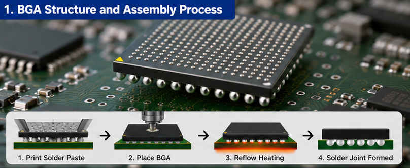
Unlike components with visible leads (QFPs, SOPs), BGAs have an array of solder balls on the bottom surface. The component is placed onto solder paste, and during reflow, the balls melt and collapse onto the PCB pads.

Key differences from standard components:

  • Joints are hidden – Cannot be visually inspected without X-ray

  • Self-centering – Surface tension during reflow can correct minor placement offsets

  • Thermal mass – Large BGAs take longer to heat than small passives

  • Warpage risk – BGA body and PCB can warp differently during reflow

  • No rework margin – A single bad joint often means removing and replacing the entire component

Common BGA package types:

 
Type Pitch Ball Diameter Typical Applications
Standard BGA 1.0-1.27mm 0.6-0.8mm Memory, FPGAs
Fine-pitch BGA 0.5-0.8mm 0.3-0.5mm Mobile processors
Ultra-fine-pitch (CSP) 0.3-0.5mm 0.2-0.3mm Smartphones, wearables
Large body BGA 30-50mm+ 0.5-0.8mm GPUs, ASICs, automotive

BGA Handling and Moisture Sensitivity

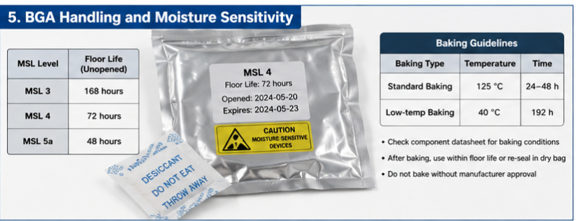
Most BGAs are moisture-sensitive. They absorb moisture from the air, and during reflow, trapped moisture turns to steam and can crack the component internally. This is called "popcorning."

MSL ratings for BGAs: Typically MSL 3, 4, or 5a (see previous article on MSL).

Handling rules:

  • Store unopened BGAs in sealed dry bags with desiccant

  • Label with floor life expiration date when opened

  • If floor life expires, bake before reflow (typically 125°C for 24-48 hours – check component datasheet)

  • Do not bake BGAs with internal moisture-sensitive construction without manufacturer approval

Baking guidelines:

  • Standard baking: 125°C for 24-48 hours

  • Low-temperature baking (for components that cannot tolerate 125°C): 40°C for 192 hours

  • After baking, use within the floor life period or re-seal in dry bag


BGA Placement Considerations

Placement accuracy requirement:

BGA placement is more forgiving than fine-pitch QFPs because surface tension during reflow pulls the component into alignment. However, there are limits.


BGA Pitch Recommended Placement Accuracy Notes
1.0mm ±0.1mm Very forgiving
0.8mm ±0.08mm Standard requirement
0.5mm ±0.05mm Requires good machine calibration
0.4mm and below ±0.03mm Challenging; requires high-precision machine

Placement force:

BGAs are heavy. Excessive placement force can squeeze paste out from under the component, causing bridging. Insufficient force may not seat the component properly.

  • Typical placement force: [X] grams (see component datasheet or machine manual)

  • Force monitoring: Use closed-loop force control if your machine has it

  • Test method: Place a BGA, then remove it and inspect paste pattern – should be evenly distributed with no paste squeezed completely out

Vision alignment:

Most pick-and-place machines use one of two methods for BGA alignment:

  1. Ball recognition – The vision system detects the outer balls and calculates the center. Most accurate but slower.

  2. Body recognition – The vision system detects the component body outline. Faster but less accurate for components with non-square ball arrays.

Recommendation: Use ball recognition for fine-pitch BGAs (0.5mm and below). Use body recognition for large-pitch BGAs where placement tolerance is wider.


Solder Paste for BGAs

BGA assembly requires paste that can:

  • Print cleanly at fine pitch (if stencil printing is used)

  • Provide sufficient flux activity to wet BGA balls

  • Minimize voids

Paste selection considerations:

  • Powder type: Type 4 or Type 5 for fine-pitch BGAs (0.5mm and below)

  • Flux type: No-clean is standard; water-washable may be used if post-reflow cleaning is required

  • Void reduction: Some pastes are formulated specifically to reduce BGA voids – ask your paste supplier

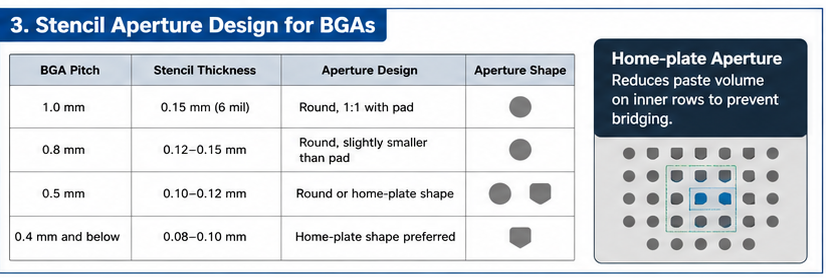
Stencil design for BGAs:


BGA Pitch Stencil Thickness Aperture Design
1.0mm 0.15mm (6 mil) Round, 1:1 with pad
0.8mm 0.12-0.15mm Round, slightly smaller than pad
0.5mm 0.10-0.12mm Round or home-plate shape
0.4mm 0.08-0.10mm Home-plate shape preferred

Home-plate aperture: A pad shape that reduces paste volume on the inner rows of a BGA. This compensates for the tendency of inner balls to bridge due to paste squeeze-out.


Reflow Profiling for BGAs

BGAs have large thermal mass. They heat up more slowly than small passives on the same board. This thermal lag is the biggest challenge in BGA reflow.

Key considerations:

1. Delta T across the BGA

The temperature difference between the center and edge of a large BGA can be significant during reflow. If one side melts before the other, the component can warp (dynamic warpage), causing head-in-pillow or open joints.

Target: <5°C delta T across the BGA during time above liquidus (TAL)

How to achieve:

  • Use multiple thermocouples on the BGA (center, corner, edge)

  • Extend soak time to equalize temperature

  • Consider a longer, lower-temperature preheat to reduce thermal shock

2. Time above liquidus (TAL)

BGA balls need sufficient time to fully collapse and wet to the PCB pads.

Typical TAL for BGAs: 60-90 seconds (compared to 45-75 seconds for standard components)

3. Peak temperature

The BGA body temperature must reach the paste melting point, but not exceed the component's maximum rating.

Typical peak for lead-free: 235-245°C (check BGA datasheet – some BGAs have lower maximums)

4. Ramp rates

Slow ramp rates reduce the risk of BGA warpage and moisture damage.

Recommended ramp rate: 1.5-2.5°C/s (slower is safer for large BGAs)


Common BGA Defects and Causes

Head-in-Pillow (HiP)

The BGA ball melts but does not collapse into the solder paste. The joint looks like a ball sitting in a shallow depression – the "head" on a "pillow."

Causes:

  • BGA warpage during reflow (balls lift away from paste)

  • Insufficient paste volume

  • Paste flux too weak (old or poorly stored paste)

  • TAL too short

  • Delta T too high across the BGA

Prevention:

  • Extend TAL to 70-90 seconds

  • Reduce delta T (improve thermal uniformity)

  • Use fresh, properly stored paste

  • Consider a BGA with lower warpage specification

Voids

Air pockets trapped inside the solder joint. Small voids are generally acceptable; large voids reduce mechanical strength and thermal conductivity.

Causes:

  • Outgassing from PCB or component

  • Paste moisture (poor storage or conditioning)

  • Flux residue trapped during solidification

Acceptable void limits (IPC-7095):

  • Void diameter <50% of ball diameter generally acceptable

  • Total void area <25% of joint area for critical applications

Prevention:

  • Bake PCBs before assembly (moisture in PCB laminate)

  • Use void-reducing paste formulation

  • Optimize reflow profile (longer soak, appropriate peak)

Bridging

Solder connects two adjacent balls.

Causes:

  • Too much paste (stencil too thick or apertures too large)

  • Excessive placement force (paste squeezed out)

  • Peak temperature too high (solder flows too far)

Prevention:

  • Reduce stencil thickness or aperture size

  • Reduce placement force

  • Lower peak temperature by 5-10°C

Open Joint (Ball Not Connected)

A ball fails to wet to the PCB pad.

Causes:

  • Missing or insufficient paste

  • Oxidized BGA ball or PCB pad

  • BGA warpage (ball never contacts paste)

  • Insufficient TAL

Prevention:

  • Inspect paste print before placement

  • Ensure proper storage of BGAs and PCBs

  • Extend TAL

  • Verify BGA flatness


BGA Rework – When Things Go Wrong

BGA rework requires specialized equipment and training. It is not recommended for inexperienced operators.

Basic rework process:

  1. Preheat the board from below to prevent thermal shock

  2. Remove the defective BGA using a hot air nozzle matched to component size

  3. Clean pads with solder wick and flux

  4. Apply fresh solder paste or flux to pads

  5. Place new BGA (or reballed original)

  6. Reflow using a local profile

  7. Inspect with X-ray

When to reball vs. replace:

  • Reball – Expensive or hard-to-source BGAs where the component itself is still good

  • Replace – Inexpensive BGAs or where the component may have been damaged

Rework success rate: With proper equipment and training, 90-95% first-pass rework success is achievable. Without proper equipment, expect 50% or less.


X-Ray Inspection for BGAs

Because BGA joints are hidden, X-ray inspection is essential for process validation and quality control. (See next article for detailed X-ray guidance.)

What X-ray reveals:

  • Bridging

  • Missing balls

  • Voids

  • Head-in-pillow (difficult – requires angled X-ray)

  • Ball size and shape consistency

Inspection frequency:

  • Process setup: 100% inspection of first board

  • Production: Periodic sampling (every [X] boards, per customer requirement)

  • Rework: 100% inspection of reworked board


BGA Design for Assembly (DFA) Tips

Problems that start in design cannot be fixed in assembly.

  • Pad design: Solder mask defined (SMD) vs. non-solder mask defined (NSMD) – NSMD generally preferred for fine-pitch BGAs

  • Via placement: No vias under BGA pads without tenting or plugging (solder can wick away)

  • Thermal relief: Ensure adequate thermal vias for heat dissipation

  • Board support: Add support pins under BGA locations to prevent board flex during placement


Conclusion

BGA assembly is challenging but manageable with proper process control. Focus on four areas:

  1. Handling – Protect moisture-sensitive BGAs with proper storage and baking

  2. Placement – Accurate enough for self-centering to work; not so heavy that paste squeezes out

  3. Reflow – Manage delta T across large BGAs; extend TAL to 60-90 seconds

  4. Inspection – Use X-ray to verify joints; don't guess

The most common BGA defect – head-in-pillow – is almost always a reflow problem (warpage or insufficient TAL) or a paste problem (weak flux). Solve those, and most BGA issues disappear.

Invest in good reflow profiling with multiple thermocouples on BGAs. And if you assemble BGAs regularly, X-ray inspection is not optional – it is essential.

Atpakaļ uz emuāru

Ievietojiet komentār

Lūdzu, ņemiet vērā, ka komentāri ir jāapstiprina pirms to publicēšanas