Introduction
Every smartphone, LED light, automotive control unit, and industrial PCB starts with thousands of tiny electronic components that must be placed onto a circuit board with incredible speed and accuracy. Completing this task manually would be slow, expensive, and nearly impossible for modern electronics manufacturing. That's where the pick and place machine comes in.
A pick and place machine is the core equipment of an SMT (Surface Mount Technology) production line. It automatically picks components from feeders and places them onto printed circuit boards (PCBs) with micron-level precision, enabling manufacturers to produce everything from LED lighting products to automotive electronics and consumer devices at high speed and consistent quality.
But what actually happens inside the machine? How does it know where every component belongs, and how can it place tens of thousands of components every hour without making mistakes?
In this guide, we'll walk through the complete pick and place process—from PCB loading to finished assembly—and explain how each step contributes to fast, accurate, and reliable SMT production.
What Is a Pick and Place Machine?
A pick and place machine is an automated system designed to mount surface-mount components onto PCBs after solder paste printing.
Using high-speed motion control, vision systems, precision nozzles, and intelligent software, the machine accurately places components ranging from tiny 0201 chips to large ICs, connectors, LEDs, and BGAs.
Today, pick and place machines are widely used in industries such as:
- LED Lighting
- Consumer Electronics
- Automotive Electronics
- New Energy
- Industrial Control
- Medical Devices
- Communication Equipment
Regardless of the application, every placement follows the same basic workflow.
Step 1: PCB Loading
Everything starts with a bare PCB arriving from the solder paste printer.
The conveyor automatically transports the PCB into the placement machine. Sensors detect the incoming board, stop it at the correct position, and clamp it securely to prevent movement during placement.
Even a tiny shift in PCB position can lead to inaccurate placement, especially when mounting fine-pitch ICs or miniature components. That's why precise board positioning is the foundation of the entire process.
Step 2: Fiducial Recognition
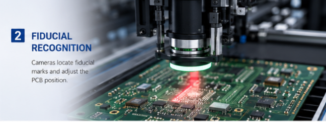
Before placing the first component, the machine must confirm the exact position of the PCB.
Using high-resolution cameras, it locates fiducial marks—small reference points designed into the PCB.
The vision system measures any slight deviation caused by printing tolerances or conveyor positioning and automatically compensates for it. This ensures every placement coordinate matches the actual board position rather than relying solely on programmed values.
Without fiducial correction, placement accuracy would quickly decrease as PCB complexity increases.
Step 3: Component Feeding
While the PCB is being aligned, components are already prepared for pickup.
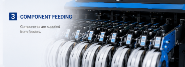
Modern SMT machines support multiple feeder types, including:
- Tape feeders
- Tray feeders
- Stick feeders
- Vibratory feeders for odd-form components
Each feeder presents components in a precise pickup position, allowing the placement head to retrieve them quickly without interrupting production.
A machine may carry dozens—or even hundreds—of feeders simultaneously, enabling multiple component types to be mounted in a single production cycle.
Step 4: Component Pickup
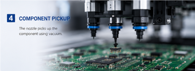
Once the required component reaches the pickup position, the placement head moves above the feeder.
A vacuum nozzle descends, picks up the component using negative pressure, and immediately lifts it for inspection.
Different components require different nozzle sizes and vacuum settings. Tiny resistors, LEDs, large ICs, and connectors all use dedicated nozzles to ensure stable handling without damage.
Modern pick and place machines automatically change nozzles during production, allowing them to handle a wide variety of component sizes without manual intervention.
Step 5: Vision Inspection and Alignment
Picking up a component isn't enough—it must also be correctly oriented.
As the placement head moves toward the PCB, the component passes over a vision camera.
The vision system checks:
- Component orientation
- Rotation angle
- Center position
- Package dimensions
- Pickup quality
If the component is slightly rotated or offset, the software calculates the correction in real time before placement.
This inspection process happens within milliseconds and is one of the key reasons modern SMT equipment can achieve both high speed and exceptional placement accuracy.
Step 6: High-Speed Placement
With alignment complete, the placement head moves to the target coordinates and lowers the component onto the solder paste.
The solder paste provides temporary adhesion, holding the component in place until reflow soldering.
Placement speed depends on several factors, including:
- Component size
- Placement distance
- Head configuration
- Motion control system
- PCB complexity
High-speed machines can place tens of thousands of components per hour while maintaining excellent repeatability.
Rather than simply moving faster, advanced motion algorithms optimize travel paths so the placement head spends less time accelerating, stopping, and changing direction.
Step 7: Continuous Production
After one component is placed, the process immediately repeats.
The placement head continuously switches between feeders and PCB positions, mounting components according to the programmed sequence.
Multiple placement heads may work simultaneously, allowing different components to be picked and placed in parallel.
Modern machines are designed to minimize idle time, ensuring the placement head is almost always performing a productive task rather than waiting.
This optimized workflow is what allows today's SMT factories to achieve extremely high production efficiency.
Step 8: PCB Unloading
Once all components have been mounted, the board clamp releases automatically.
The conveyor transports the completed PCB to the next process, typically the reflow oven, where solder paste melts and permanently bonds each component to the board.
After reflow, the PCB may undergo AOI, SPI, X-ray inspection, or functional testing before moving to final assembly.
What Determines Placement Accuracy?
Many people assume accuracy depends only on the machine itself, but several factors work together.
These include:
- Stable machine frame
- High-resolution vision system
- Precision linear motors
- Servo motion control
- Quality feeders
- Proper nozzle selection
- Accurate PCB alignment
- Optimized software algorithms
When all of these elements operate together, modern SMT machines can consistently achieve micron-level placement precision.
Why High-Speed Placement Doesn't Mean Lower Accuracy
A common misconception is that increasing speed reduces precision.
In reality, modern pick and place machines improve both simultaneously.
Advanced motion control minimizes vibration during rapid acceleration, while intelligent vision systems continuously compensate for position deviations.
As a result, manufacturers no longer have to choose between speed and accuracy. With the right equipment, they can achieve both.
Applications Across Different Industries
Although the placement process remains largely the same, different industries present unique production requirements.
LED lighting manufacturers often focus on maximizing throughput for products such as LED strips, DOB modules, panel lights, and bulb driver boards.
Automotive electronics demand exceptional placement accuracy and process stability due to strict quality standards.
Consumer electronics manufacturers prioritize flexibility, enabling quick product changeovers while maintaining high production efficiency.
Industrial control and communication equipment frequently involve larger boards with mixed component types, requiring machines capable of handling everything from tiny chip components to large connectors and BGAs within a single program.
Conclusion
A pick and place machine does far more than simply move components from one location to another. It combines precision mechanics, intelligent software, high-speed vision inspection, and advanced motion control into a fully automated process capable of placing thousands of components every hour with remarkable consistency.
From PCB loading and fiducial recognition to component pickup, vision alignment, placement, and final unloading, every step is designed to maximize efficiency while maintaining exceptional accuracy.
As electronic products continue to become smaller, faster, and more complex, the role of the pick and place machine will only become more critical. Choosing equipment that delivers the right balance of speed, precision, flexibility, and reliability is essential for manufacturers looking to improve productivity and stay competitive in today's electronics industry.
|